There are two ways that computer components can transfer data.
One option is to have a point-to-point connection, a private set of wires that connects two components to each other. This allows a very high speed communication, but it makes a more complicated board.
The other approach is a “Bus”. A bus connects many devices to each other over a shared set of wires. It operates like the traditional telephone system. Every house is connected to the phone system and is assigned a numeric ID (the phone number). Any phone can communicate with any other phone using the number, then hang up and call someone else.
The first PC in 1981 had a single bus that connected everything. The CPU, memory, and every I/O device all connected to the common bus. That unified bus design survived through the second generation PC AT. However, eventually the speed of computer memory outstripped the common speed used by all the devices. The PC connected the CPU to the memory using a private memory bus, and that started a process of specialization. Today most devices are connected by private point to point wires that connect to “the chipset” on the mainboard. The chipset allows these devices to talk to each other, but since it happens inside a chip, that isn’t technically a ‘bus” architecture.
First, consider the core computer components:
- The mainboard is now controlled by the “chipset”, typically a pair of chips that connect to the CPU and all the other devices. These two chips will be connected to each other by a high speed point to point connection. AMD uses a public standard called HyperTransport. Intel created its own solution.
- The CPU socket is connected to the chipset, and in newer systems it is separately connected to memory. Depending on the type of CPU, there may be 1, 2, or 3 sets of wires connecting the CPU chip to memory buses.
- The memory is a bus because each set of wires from the CPU connects to two sockets into which you can plug two independent DIMM modules. Servers support more than two memory modules, but only by using a more expensive system of buffers and registers that allows greater timing flexibility.
- A Server can also have more than one CPU socket. It is relatively simply to add a second socket, in which case the two CPUs either talk to each other over a direct point to point connection or else they talk to each other through one of the chipset chips. AMD has a design that allows for up to eight sockets to be on the same board. Because CPU to CPU communication requires speeds that cannot be achieved over a bus, larger groups of sockets have point to point connections with a forwarding mechanism, where if two CPUs are not directly connected to each other they can communicate through a third CPU socket to which they are both connected. The middle CPU receives and forwards data and requests.
Many of the devices that in the first PC were separately connected to the bus are, in a modern PC, managed by the Southbridge chip. The keyboard, mouse, serial port, parallel (printer) port, disks, LAN, audio, and sometimes the video are all internally controlled by the chip with whatever internal connections the chip chooses to provide. Signals from the Southbridge chip are then distributed throughout the mainboard to connect to various other cables and connectors.
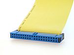
The old “Parallel” ATA (IDE) is a bus that transfers data down the flat ribbon cable to up to two disk devices at 100 Megabytes per second (Mb/s).

The new Serial ATA connector and cable is a point to point connection to one disk that operates at 300 or (in newer systems) 600 Megabytes per second. Most physical disks cannot transfer data faster than 100 MB/s anyway, but new SSD disks can reach 200 MB/s and use the extra speed.

The mainboard may have one to three old PCI adapter card slots. This is a bus because all the slots share the same communication wires. The bus transfers 32 bits (4 bytes) every tick of a 33 MHz clock and therefore has a rate of 133 Mb/s. Servers may have a larger version of this slot that transfers 64 bits every tick of a 66 or 100 MHz clock.

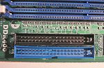
The new standard for adapter cards is PCI-e. As you can see from the picture, PCIe slots are not all the same size like PCI slots are. That is because each slot is connected to one or more point to point pairs of data signaling wires called a “line”. Each line operates at 250 megabytes per second (in both directions simultaneously), and they add up so two lines is 500 MB/s and so on. The size of the slot indicates the maximum number of lines that can be connected. In this picture, the top slot is x4 and can connect to 4 lines, the next slot is x16 and can connect to 16 lines, and then there is an x1 and a second x16.
A card has a size just like the slot has a size. You can plug a smaller card into a larger slot, but not the reverse. However, while the size of the slot determines the maximum number of line that can be connected to it, the slot may be physically connected to fewer lines than the maximum. For example, an x4 slot may actually only have two active lines, and an x16 slot may only have 8 active lines. At boot time the system uses the smaller number of lines connected to the slot and the number of lines supported by the card.

A USB port connects the PC to an external slow or medium speed device. USB 2.0 can operate at 480 megabits per second, which superficially translates to 60 megabytes per second except that the communications protocol is not that efficient and so you are not likely to see real transfer faster than 40 MB/s. The cable appears to be point to point, but the two sockets share a common controller with limited bandwidth.
Trends
Most computer components operate at speeds that no longer permit the type of shared wires and signaling provided by a bus architecture. However, different speeds and requirements produce different custom solutions. The HyperTransport that connect an AMD CPU chip to the chipset and to other CPU sockets (on a server) is different from the PCIe lines that connect the chipset to adapter cards, which in turn are different from the SATA cable that connects the chipset to a hard disk. The original PC had a single unified bus because that was all that the technology could support at the time. Now we can afford a more complicated set of specialized solutions.